Question 19
You are troubleshooting an issue with a pair of Aruba CX 8360 switches configured with VSX Each switch has multiple VRFs. You need to find the IP address of a particular client device with a known MAC address You run the "show arp" command on the primary switch in the pair but do not find a matching entry for the client MAC address.
The client device is connected to an Aruba CX 6100 switch by VSX LAG. Which action can be used to find the IP address successfully?
A)
B)
C)
D)
Correct Answer:B
The show arp command displays the ARP table for a specific VRF or all VRFs on the switch. The ARP table contains the IP address to MAC address mappings for hosts that are directly connected to the switch or reachable through a gateway. If the client device is connected to another switch by VSX LAG, the ARP entry for the client device will not be present on the primary switch unless it has communicated with it recently. Therefore, to find the IP address of the client device, the administrator should run the show arp command on the secondary switch in the VSX pair, specifying the VRF name that contains the client device??s subnet. References: https://techhub.hpe.com/eginfolib/Aruba/OS-CX_10.04/5200-6692/GUID-9B8F6E8F-9C7A-4F0D-AE7B-9D8E6C5B6A7F.html
Question 20
You must ensure the HPEAruba network you are configuring for a client is capable of plug- and-play provisioning of access points. What enables this capability?
Correct Answer:A
The capability that enables plug-and-play provisioning of access points in an HPE Aruba network is the UCC Service. The UCC Service is a cloud-based service that allows the access points to automatically discover and connect to the Aruba Central management platform without any manual intervention. The UCC Service also provides zero-touch configuration, firmware updates, and monitoring for the access points1.
The other options are incorrect because:
✑ B. LLDP-MED: LLDP-MED is a protocol that enhances the interoperability between
network devices and IP phones. It does not enable plug-and-play provisioning of access points2.
✑ C. SRTP: SRTP is a protocol that provides encryption and authentication for voice
and video traffic. It does not enable plug-and-play provisioning of access points3.
✑ D. CSMA: CSMA is a protocol that regulates how devices share a common medium, such as a wireless channel. It does not enable plug-and-play provisioning of access points.
Question 21
DRAG DROP
Match the topics with the underlying technologies (Options may be used more than once or not at all.)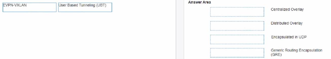
Solution: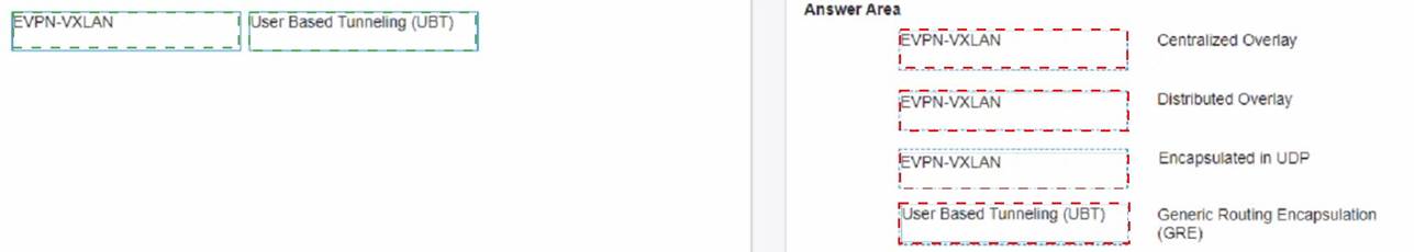
Does this meet the goal?
Correct Answer:A
Question 22
Which statements regarding 0SPFv2 route redistribution are true for Aruba OS CX switches? (Select two.)
Correct Answer:AE
These are two correct statements regarding OSPFv2 route redistribution for Aruba OS CX switches. Route redistribution is a process that allows routes from one routing protocol or source to be injected into another routing protocol or destination. OSPFv2 is a link-state routing protocol that supports route redistribution from various sources, such as connected, static, BGP, etc. The ??redistribute connected?? command will redistribute all connected routes for the switch, including local loopback addresses, into OSPFv2. The ??redistribute static route-map connected-routes?? command will redistribute all static routes that have a matching permit statement in the route map named ??connected- routes?? into OSPFv2. The other statements are incorrect because they either do not reflect the correct behavior of route redistribution commands or do not exist as valid commands. References: https://www.arubanetworks.com/techdocs/AOS-CX/10.04/HTML/5200- 6728/bk01-ch02.html https://www.arubanetworks.com/techdocs/AOS- CX/10.04/HTML/5200-6728/bk01-ch03.html
Question 23
A customer is using a legacy application that communicates at layer-2. The customer would like to keep this application working to a remote site connected via layer-3 All legacy devices are connected to a dedicated Aruba CX 6200 switch at each site.
What technology on the Aruba CX 6200 could be used to meet this requirement?
Correct Answer:A
VXLAN is a technology that can be used to meet the requirement of using a legacy application that communicates at layer-2 across a layer-3 network. Static VXLAN is a feature that allows the creation of layer-2 overlay networks over a layer-3 underlay network using VXLAN tunnels. Static VXLAN does not require any control plane protocol or VTEP discovery mechanism, and can be configured manually on the Aruba CX 6200 switches. The other options are incorrect because they either do not support layer-2 communication over layer-3 network or are not supported by Aruba CX 6200 switches. References: https://www.arubanetworks.com/techdocs/AOS-CX/10.04/HTML/5200- 6728/bk01-ch03.html https://www.arubanetworks.com/techdocs/AOS- CX/10.04/HTML/5200-6728/bk01-ch05.html
Question 24
Refer to Exhibit: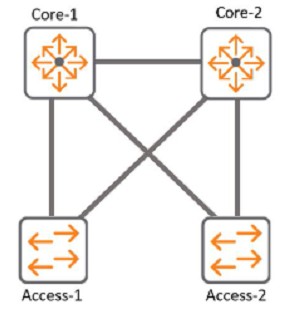
With Access-1, What needs to be identically configured With MSTP to load-balance VLANS?
Correct Answer:B
The correct answer is B. Spanning-tree instance VLAN mapping.
To load-balance VLANs with MSTP, you need to configure the same VLAN-to-instance mapping on all switches in the same MST region. This means that you need to assign different VLANs to different MST instances, and then adjust the spanning tree parameters (such as priority, cost, or port role) for each instance to achieve the desired load balancing. For example, you can make one switch the root for instance 1 and another switch the root for instance 2, and then map half of the VLANs to instance 1 and the other half to instance 2.
According to the Cisco document Understand the Multiple Spanning Tree Protocol (802.1s), one of the steps to configure MST is:
✑ Split your set of VLANs into more instances and configure different MST settings for each of these instances. In order to easily achieve this, elect Bridge D1 to be the root for VLANs 501 through 1000, and Bridge D2 to be the root for VLANs 1 through 500. These statements are true for this configuration:
Switch D1(config)#spanning-tree mst configuration Switch D1(config-mst)#instance 1 vlan 501-1000 Switch D1(config-mst)#exit
Switch D1(config)#spanning-tree mst 1 priority 0
Switch D2(config)#spanning-tree mst configuration Switch D2(config-mst)#instance 2 vlan 1-500 Switch D2(config-mst)#exit
Switch D2(config)#spanning-tree mst 2 priority 0
The above commands create two MST instances, 1 and 2, and map VLANs 501-1000 to instance 1 and VLANs 1-500 to instance 2. Then, they make switch D1 the root for instance 1 and switch D2 the root for instance 2.
The other options are incorrect because:
✑ A. Spanning-tree bpdu-guard setting is a security feature that disables a port if it receives a BPDU from an unauthorized device. It does not affect load balancing with MSTP.
✑ C. Spanning-tree CIST mapping is not a valid command. CIST stands for Common and Internal Spanning Tree, which is the spanning tree instance that runs within an MST region and interacts with other regions or non-MST switches.
✑ D. Spanning-tree root-guard setting is another security feature that prevents a port from becoming a root port if it receives superior BPDUs from another switch. It does not affect load balancing with MSTP.